MULTIPLEXING
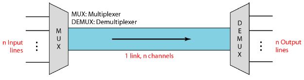
Whenever the bandwidth of a medium linking two devices is greater than the bandwidth needs of the devices, the link can be shared. Multiplexing is the set of techniques that allows the simultaneous transmission of multiple signals across a single data link. As data and telecommunications use increases, so does traffic.
Topics discussed in this section:
- Frequency-Division Multiplexing
- Wavelength-Division Multiplexing
- Synchronous Time-Division Multiplexing
- Statistical Time-Division Multiplexing
Dividing a link into channels
Categories of multiplexing

Frequency-Division Multiplexing
Frequency-division multiplexing (FDM) is an analog technique that can be applied when the bandwidth of a link (in hertz) is greater than the combined bandwidths of the signals to be transmitted.
- In FDM, signals generated by each sending device modulate different carrier frequencies.
- These modulated signals are then combined into a single composite signal that can be transported by the link.
- Carrier frequencies are separated by sufficient bandwidth to accommodate the modulated signal.
- Channels can be separated by strips of unused bandwidthguard bands-to prevent signals from overlapping.
- Carrier frequencies must not interfere with the original data frequencies.
Frequency-division multiplexing

Note
FDM is an analog multiplexing technique
that combines analog signals.
FDM: Multiplexing Process
- Each source generates a signal of a similar frequency range.
- Inside the multiplexer, these similar signals modulates different carrier frequencies (f1, f2, f3..).
- The resulting modulated signals are then combined into a single composite signal that is sent out over a media link that has enough bandwidth to accommodate it.
FDM process

FDM: De-multiplexing Process
- The de-multiplexer uses a series of filters to decompose the multiplexed signal into its constituent component signals.
- The individual signals are then passed to a demodulator that separates them from their carriers and passes them to the output lines.
FDM de-multiplexing example

AT&T Analog hierarchy

FDM:Application
- A very common application of FDM is AM and FM radio broadcasting. A special band from 530 to 1700 kHz is assigned to AM radio.each AM station needs 10kHz of bandwidth. FM has a wider band of 88 to 108 MHz because each station needs a bandwidth of 200 kHz.
- Another common use of FDM is in television broadcasting. Each TV channel has its own bandwidth of 6 MHz.
- The first generation of cellular telephones (still in operation) also uses FDM.
Wavelength-Division Multiplexing
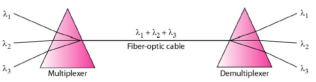
Wavelength-division multiplexing (WDM) is designed to use the high-data-rate capability of fiber-optic cable.
WDM is conceptually the same as FDM, except that the multiplexing and demultiplexing involve optical signals transmitted through fiber-optic channelss.
The idea is the same: We are combining different signals of different frequencies. The difference is that the frequencies are very high.
Wavelength-division multiplexing

Note
WDM is an analog multiplexing
technique to combine optical signals.
Prisms in wavelength-division multiplexing and de-multiplexing
WDM:Application
One application of WDM is the SONET network in which multiple optical fiber lines are multiplexed and demultiplexed.
Time-Division Multiplexing
Time-division multiplexing (TDM) is a digital process that allows several connections to share the high bandwidth of a line.
- Instead of sharing a portion of the bandwidth as in FDM, time is shared.
- Each connection occupies a portion of time in the link.
- TDM is, in principle, a digital multiplexing technique, Digital data from different sources are combined into one timeshared link.
- We can divide TDM into two different schemes: synchronous and statistical.
TDM

Note
TDM is a digital multiplexing technique
for combining several low-rate
channels into one high-rate one.
Synchronous TDM
In synchronous TDM, the data flow of each input connection is divided into units, where each input occupies one input time slot. A unit can be 1 bit, one character, or one block of data. Each input unit becomes one output unit and occupies one output time slot.
- Time slots are grouped into frames. A frame consists of one complete cycle of time slots, with one slot dedicated to each sending device.
- If we have n connections, a frame is divided into n time slots and one slot is allocated for each unit, one for each input line.
- If the duration of the input unit is T, the duration of each slot is T/n and the duration of each frame is T.
- The data rate of the output link must be n times the data rate of a connection to guarantee the flow of data.
Synchronous time-division multiplexing

Note
In synchronous TDM, the data rate
of the link is n times faster, and the unit
duration is n times shorter.
TDM-Interleaving
- TDM can be visualized as two fast-rotating switches, one on the multiplexing side and the other on the demultiplexing side.
- The switches are synchronized and rotate at the same speed, but in opposite direction.
- On the multiplexing side, as the switch opens in front of a connection, that connection has the opportunity to send a unit onto the path. This process is called interleaving.
- On the demultiplexing side, as the switch opens in front of a connection, that connection has the opportunity to receive a unit from the path.
Interleaving

Empty slots
If a source does not have data to send, the corresponding slot in the output frame is empty.
Empty slots
TDM-Data Rate Management
One problem with TDM is how to handle a disparity in the input data rates.
If data rates are not the same, three strategies, or a combination of them, can be used.
- Multilevel multiplexing,
- Multiple-slot allocation, and
- Pulse stuffing.
Multilevel multiplexing
Multilevel multiplexing is a technique used when the data rate of an input line is a multiple of others.
Multilevel multiplexing

Multiple-slot multiplexing
Multiple multiplexing is a technique used to allot more than one slot in a frame to a single input line
Multiple-slot multiplexing

Pulse stuffing
Sometimes the bit rates of sources are not multiple integers of each other. Then to make the data rate compatible , dummy bits are added to input lines . This technique is called pulse stuffing, bit padding, or bit stuffing.
Pulse stuffing

Frame Synchronization
- Synchronization between the multiplexer and demultiplexer is a major issue.
- If the. multiplexer and the demultiplexer are not synchronized, a bit belonging to one channel may be received by the wrong channel.
- For this reason, one or more synchronization bits are usually added to the beginning of each frame. These bits, called framing bits.
- Framing bits, follow a pattern, frame to
- Frame, that allows the demultiplexer to synchronize with the incoming stream so that it can separate the time slots accurately.
- In most cases, this synchronization information consists of 1 bit per frame, alternating between 0 and 1
Framing bits

Digital hierarchy

DS and T line rates

T-1 line for multiplexing telephone lines

T-1 frame structure

E line rates

Statistical TDM
- In synchronous TDM, each input has a reserved slot in the output frame. This can be inefficient if some input lines have no data to send.
- In statistical time-division multiplexing, slots are dynamically allocated to improve bandwidth efficiency.
- Only when an input line has a slot's worth of data to send is it given a slot in the output frame.
- In statistical multiplexing, the number of slots in each frame is less than the number of input lines.
- The multiplexer checks each input line in round-robin fashion; it allocates a slot for an input line if the line has data to send; otherwise, it skips the line and checks the next line.
TDM slot comparison

Addressing
- In statistical TDM, a slot needs to carry data as well as the address of the destination.
- The addressing in its simplest form can be n bits to define different output lines with n = log2 N.
- For example, for eight different output lines, we need a 3-bit address.
Slot Size
- Since a slot carries both data and an address in statistical TDM, the ratio of the data size to address size must be reasonable to make transmission efficient.
- For example, it would be inefficient to send 1 bit per slot as data when the address is 3 bits.
- In statistical TDM, a block of data is usually many bytes while the address is just a few bytes.
No Synchronization Bit
The frames in statistical TDM need not be synchronized, so we do not need synchronization bits.
Bandwidth
- In statistical TDM, the capacity of the link is normally less than the sum of the capacities of each channel.
- The designers of statistical TDM define the capacity of the link based on the statistics of the load for each channel.
- If on average only x percent of the input slots are filled, the capacity of the link reflects this. Of course, during peak times, some slots need to wait.