LINE CODING SCHEMES
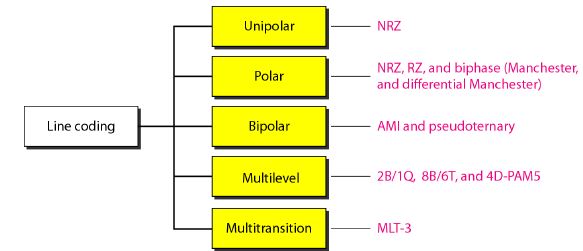
We can roughly divide line coding schemes into five broad categories, as shown in Figure 4.
Line coding schemes
Unipolar Scheme
In a unipolar scheme, all the signal levels are on one side of the time axis, either above or below.
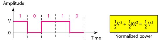
Unipolar NRZ scheme
 Note
Note


Bipolar schemes: AMI and pseudoternary


Line coding schemes

Unipolar Scheme
In a unipolar scheme, all the signal levels are on one side of the time axis, either above or below.
- NRZ (Non-Return-to-Zero)
In this scheme,positive voltage defines bit 1 and the zero voltage defines bit 0. It is called NRZ because the signal does not return to zero at the middle of the bit.
Unipolar NRZ scheme

Unipolar-NRZ analysis
The scheme is simple to to implement, and has the following characteristics:
DC bias: Because all of the signals are the same polarity, the line can develop significant DC bias.
Synchronization: This scheme is not self-clocking. A long string of either ones or zeroes can result in the receiver losing track of the clock. T
Line state: A long series of zeroes cannot be distinguished from a failed circuit. To avoid this issue, many systems use a minute voltage (instead of no voltage) for representing the zero (0) bit.
Efficiency: In this encoding scheme, the bit rate is equal to the baud. Each bit is represented, at most, by a single signal transition.
Polar Scheme
In polar schemes, the voltages are on the both sides of the time axis. For example, the voltage level for 0 can be positive and the voltage level for I can be negative.
- NRZ (Non-Return-to-Zero)
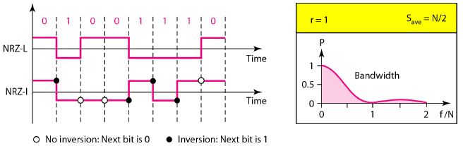
Polar NRZ-L and NRZ-I schemes
- In polar NRZ encoding, we use two levels of voltage amplitude. We can have two versions of polar NRZ: NRZLand NRZ-I.
- In NRZ-L (NRZ-Level), the level of the voltage determines the value of the bit.
- In NRZ-I (NRZ-Invert), the change or lack of change in the level of the voltage determines the value of the bit. If there is no change, the bit is 0; if there is a change, the bit is 1.
In NRZ-L the level of the voltage
determines the value of the bit.
In NRZ-I the inversion
or the lack of inversion
determines the value of the bit.
Polar-NRZ analysis
- The Baseline wandering is a problem for both variations; it is twice as severe in NRZ-L. If there is a long sequence of 1's or 0's in NRZ-L, the average signal power becomes skewed. The receiver might have difficulty discerning the bit value. In NRZ-I this problem occurs only for a long sequence of 0's. If we eliminate the long sequence of 0's, we can avoid baseline wandering.
- The synchronization problem also exists in both schemes. Again, this problem is more serious in NRZ-L than in NRZ-I. While a long sequence of as can cause a problem in both schemes, a long sequence of 1's affects only NRZ-L.
- Another problem with NRZ-L occurs when there is a sudden change of polarity in the system. For example, if twisted-pair cable is the medium, a change in the polarity of the wire results in all 0's interpreted as 1 s and all 1 s interpreted as 0's. NRZ-I does not have this problem. Both schemes have an average signal rate of NI2.
- NRZ-L and NRZ-J both have a DC component problem.
Note
NRZ-L and NRZ-J both have an average
signal rate of NI2 Baud.
RZ (Return-to-Zero)
The main problem with NRZ encoding occurs when the sender and receiver clocks are not synchronized. The receiver does not know when one bit has ended and the next bit is starting.
One solution is the return-to-zero (RZ) scheme, which uses three values: positive, negative, and zero.
In RZ, the signal changes not between bits but during the bit. In this scheme the signal goes to 0 in the middle of each bit. It remains there until the beginning of the next bit.
Polar RZ scheme

Polar-RZ analysis
- The main disadvantage of RZ encoding is that it requires two signal changes to encode a bit and therefore occupies greater bandwidth.
- Sudden change of polarity resulting in all 0s interpreted as 1's and all 1's interpreted as 0's, still exist here, but there is no DC component problem.
- Another problem is the complexity: RZ uses three levels of voltage, which is more complex to create and discern. As a result of all these deficiencies, the scheme is not used today.
Biphase: Manchester and Differential Manchester
The idea of RZ (transition at the middle of the bit) and the idea of NRZ-L are combined into the Manchester scheme.
In Manchester encoding, the duration of the bit is divided into two halves. The voltage remains at one level during the first half and moves to the other level in the second half. The transition at the middle of the bit provides synchronization.
Differential Manchester, on the other hand, combines the ideas of RZ and NRZ-I. There is always a transition at the middle of the bit, but the bit values are determined at the beginning of the bit. If the next bit is 0, there is a transition; if the next bit is 1, there is none.
Polar biphase: Manchester and differential Manchester schemes

Polar-Biphase analysis
- The Manchester scheme overcomes several problems associated with NRZ-L, and differential Manchester overcomes several problems associated with NRZ-I.
- First, there is no baseline wandering.
- There is no DC component because each bit has a positive and negative voltage contribution.
- The only drawback is the signal rate. The signal rate for Manchester and differential Manchester is double that for NRZ. The reason is that there is always one transition at the middle of the bit and maybe one transition at the end of each bit.
Note
In Manchester and differential
Manchester encoding, the transition
at the middle of the bit is used for
synchronization.
Note
The minimum bandwidth of Manchester
and differential Manchester is 2 times
that of NRZ.
Bipolar Scheme
Bipolar encoding utilises three voltage levels: positive, negative and neutral (zero). Zero is used to represent binary 0 and binary 1 is represented by alternating positive and negative voltages.
1. Alternate Mark Inversion (AMI).
- AMI is a bipolar encoding system where neutral (zero) voltage represents binary 0 and alternating positive and negative voltages represents binary 1. With this line encoding it is the alternating voltages that determine the binary ones.
2. Pseudoternary:
- This encoding scheme is same as AMI, but alternating positive and negative pulses occur for binary 0 instead of binary 1.
Note
In bipolar encoding, we use three levels: positive, zero, and negative.
Bipolar schemes: AMI and pseudoternary

Two cases of B8ZS scrambling technique3. Bipolar 8-Zero Substitution (B8ZS)
- B8ZS works in a similar way to AMI by changing poles for each binary 1.
- In AMI there is a problem with synchronization being lost when there is a stream of binary 0s being sent.
- B8ZS attempts to tackle this problem by making artificial signal changes. These signals are known as violations and occur when eight consecutive 0s occur in the bit stream.
- If octet of all zeros and last voltage pulse preceding was positive encode as 000+-0-+
- If octet of all zeros and last voltage pulse preceding was negative encode as 000-+0+-
- Causes two violations of AMI code
- Unlikely to occur as a result of noise
- Receiver detects and interprets as octet of all zeros

B8ZS analysisThis technique balances the positive and negative voltage levels (two positives and two negatives), which means that the DC balance is maintained.
This technique is Self Synchronized.4. High-density bipolar 3-zero (HDB3)
- High-density bipolar 3-zero (HDB3) is commonly used outside of North America.
- In this technique, which is more conservative than B8ZS, four consecutive zero-level voltages are replaced with a sequence of 000V or B00V.
- The reason for two different substitutions is to maintain the even number of nonzero pulses after each substitution.
The two rules can be stated as follows:
- If the number of nonzero pulses after the last substitution is odd, the substitution pattern will be 000V, which makes the total number of nonzero pulses even.
- If the number of nonzero pulses after the last substitution is even, the substitution pattern will be B00V, which makes the total number of nonzero pulses even.
Different situations in HDB3 scrambling technique

Note
HDB3 substitutes four consecutive
zeros with 000V or B00V depending
on the number of nonzero pulses after
the last substitution.
Summary of line coding schemes
